
Powerful 024v Voltage Regulator Circuit Using One Transistor Voltage regulator, Electronic
This is the circuit diagram of the voltage and current regulator circuit that can give the output of min 1.5v to max of 30v DC and current min 0 to max 10A. Use the 5k potentiometer for the adjustment of voltage and the 10k potentiometer with BD139 transistor for adjustment of current. 2 power Transistor 2N3055 is used in this circuit to.
Voltage Regulator Circuits and Projects Homemade Circuit Projects
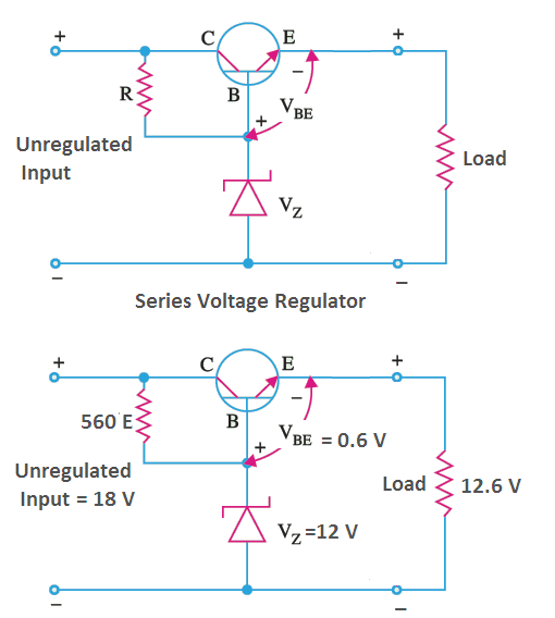
1. Zener Controlled Transistor Voltage Regulator A zener controlled voltage regulator is used when the efficiency of a regulated power supply becomes very low due to high current. There are two kinds of zener controlled transistor voltage regulators. Zener Controlled Transistor Series Voltage Regulator

Variac Variable Transformers Voltage Regulators Tdgc2 Arnaiz Electronics and Electrical Supply
load using 5V and drawing 600mA consumes 3W (P=V*I=5V*0.6A). but the regulator need to pass the same 600mA current and still take the heat for all excess voltage. at 36V input that means that transistor will need to handle (36V-5V)*0.6A=31V*0.6A = 18.6W. that is on pair with some soldering irons.
National Semiconductor LM317K Variable Voltage Regulator TO3 Transistor OMA064A Rich Electronics
A high-stability voltage regulator (VR) is proposed in this paper, which integrates transient enhancement and overcurrent protection (OCP). Taken into consideration the performance and area advantages of low-voltage devices, most control parts of proposed VR are supplied by the regulated output voltage, which forms self-power technique (SPT) with power supply rejection (PSR) boosting. Besides.
PNP Transistor Voltage Regulator
LM723 Voltage Regulator Features. It is an adjustable voltage regulator which operates in both positive or negative supply operation. Voltage can be adjusted from 2V to 37V. The maximum input voltage is 40V. Output current is 150mA without an external pass transistor. It can be increased to 10A by adding transistors externally.

Hengjiaan LM317 Adjustable Voltage Regulator Transistor Triode (10PCS) Free Shipping DealExtreme
The Transistor Series Voltage Regulator Theory is explained as follows. From the circuit of Figure, we can observe that the feedback voltage V F, is the voltage developed across the part of the potential divider P & Q.If we represent that resistance by R f, the feed back fraction will be, R f /(R f + R a) where R a is the part of the potential divider R & P as shown in figure.
Zener Diode as Voltage Regulator your electrical guide
A voltage regulator circuit using an op amp, emitter follower transistor, and Zener diode, is simple to draw from memory if you understand the working principle.. In addition, if you make R 1 a variable resistor, then the output voltage could be varied for a large range of voltages. For this op amp circuit, we use the operational amplifier.
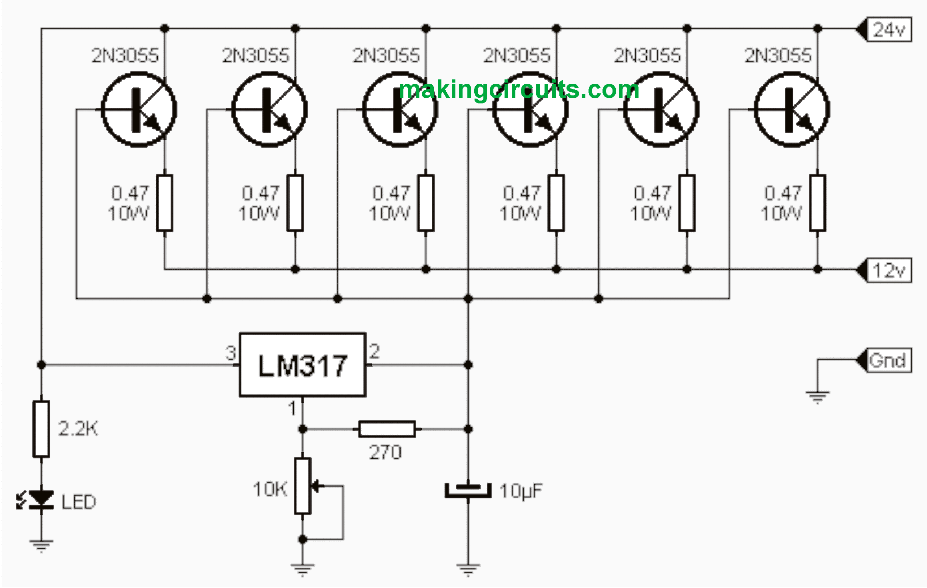
High Current LM317 Variable Power Supply Circuit
Transistor (Q1) - It helps to modify the resistance of the circuit to maintain voltage constant. Its terminals are Base, emitter and collector. The Zener diode is connected to the base of the transistor, and input is given at the collector side. The load is connected to the emitter. Let VBE be the base-emitter voltage.
LM317 Adjustable Voltage Regulator in Pakistan Electronics Hub
Here Zener diode provides the reference voltage. The transistor series voltage regulator working is when the voltage at the transistor's base voltage is held to the stable voltage across the diode. For instance, if Zener voltage is 8V, the transistor's base voltage will stay approximately 8V. Therefore, Vout = VZ - VBE.
National Semiconductor LM317K Variable Voltage Regulator TO3 Transistor OMA064A Rich Electronics
The circuit shown below is a basic series voltage regulator based on transistors. Transistor Q1 (2N 3054) and Q2 (2N 3055) form a darlington pair.. parallel with the zener diode and connecting the slider of the potentiometer to base of Q1 base will make it a simple variable bench supply, which is still in service with me. ke730 12 years ago.
0.5/1/2/3KVA Variac Variable Transformer 0130V AC Voltage Regulator 5/10/20/30A eBay
The transistor voltage regulator works based on the principle of using a variable resistor in the form of a transistor. This transistor adjusts its resistance in response to changes in input voltage or load conditions, thus maintaining a steady output voltage.

on video High power voltage regulator 0V to 30V 5A LM317 and TIP3055 Transistor electrical
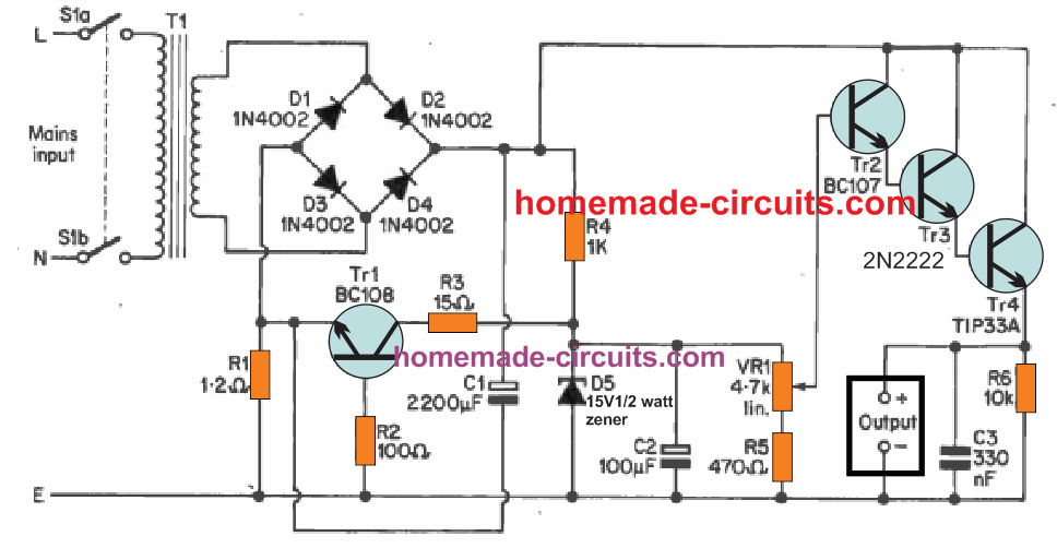
Variable Voltage, Current Power Supply Circuit Using Transistor 2N3055 Last Updated on May 13, 2022 by Swagatam 290 Comments In this post we learn how to make a simple variable power supply circuit using transistor 2N3055 and some other passive components. It includes variable voltage and variable current feature, fully adjustable.
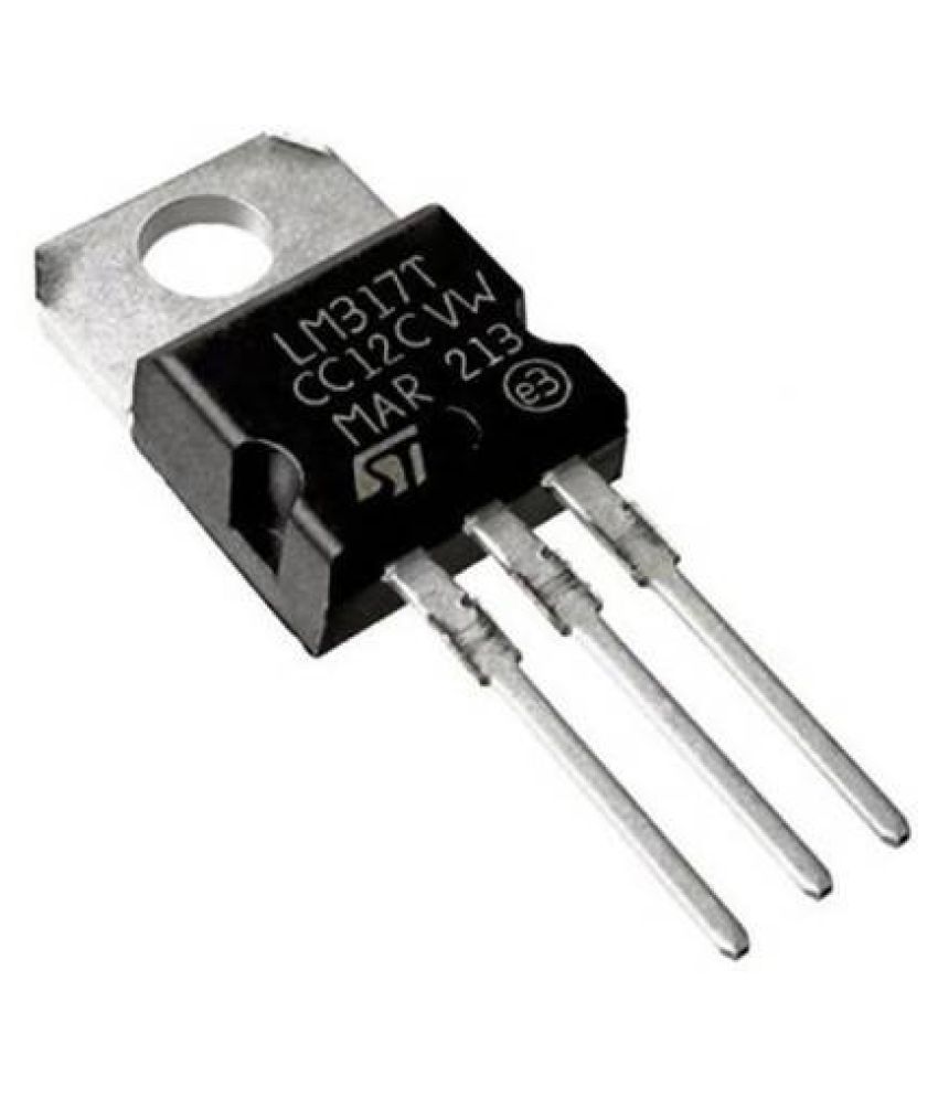
LM317T IC Adjustable Voltage Regulator FET Transistor Buy LM317T IC Adjustable Voltage
A regulator is an important device when it comes to power electronics as it controls the power output. Need for a Regulator For a Power supply to produce a constant output voltage, irrespective of the input voltage variations or the load current variations, there is a need for a voltage regulator.

Simple Voltage Regulator using 2N3055 Transistor
Simple Voltage Regulator using 2N3055 Transistor. In this DIY, we are making a simple voltage regulator using 2N3055. A voltage regulator is an electronic device that is used to regulate voltage levels. When a steady, dependable voltage is required, at that point a voltage regulator is a preferred device. Moreover, it generates a fixed output.

voltage regulator using transistor Voltage regulator, Electronics basics, Electronics circuit
Pass Element: The pass element (e.g. a transistor) acts as a variable resistance and drops the excess voltage across it. The output voltage is obtained at one terminal of the pass element. Figure 1: Variable Voltage Regulator Block Diagram Figure 1 shows the block diagram of a simple variable voltage regulator.
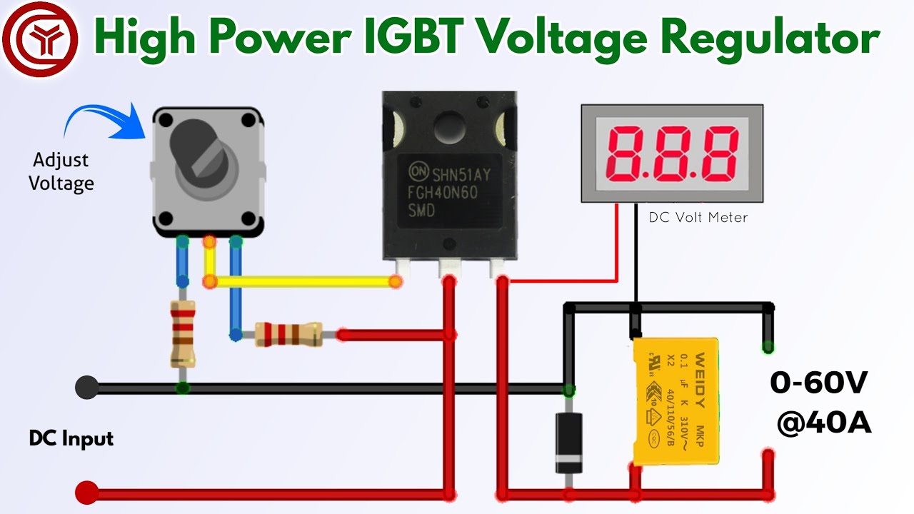
060v adjustable voltage regulator using single IGBT Transistor YouTube
Variable Voltage Regulator using Transistor This adjustable voltage regulator circuit uses a transistor, Zener diode, and potentiometer to produce a regulated output in the range 0 V to 8.5 V (at 0.5-amps max). The input voltage should be in the range 12 V to 16 V.